Author: admin (page 6 of 6)

laser welding: mold repair: machining mistake

The corner was gouged with a cutter during rough machining. The repair must completely fill this large defect, but the heat of welding cannot be allowed to distort the part and shouldn’t disrupt the copper plug that seals a waterline in this part.

The material is 420M stainless at 52 RC.

This is about as big a weld volume as can be conveniently handled by laser micro welding. Bigger weld areas are better handled with TIG, but at the risk that the part will distort.

It is possible to do the rough welding using TIG and manage areas of distortion afterward, with the laser welder.

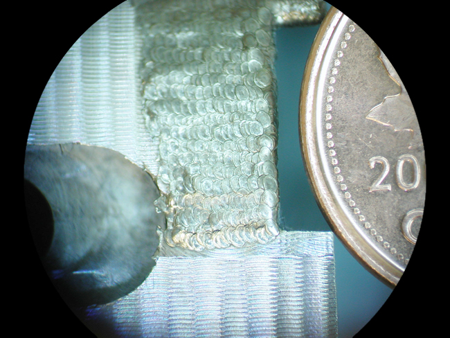
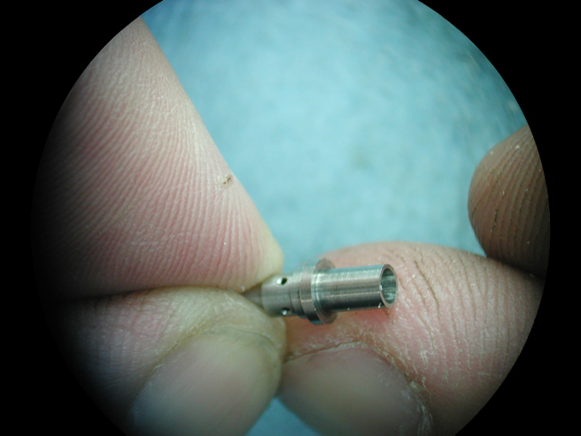
1. TOP VIEW: Note the huge number of individual welds required to fill this defect. (Each hemispherical mark you see, is formed by a discrete weld deposit using a 0.015” diameter 420 M stainless welding wire under argon gas coverage).

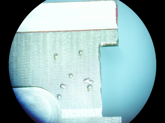
2. SIDE VIEW: The weld is about 4 layers deep at its thickest.

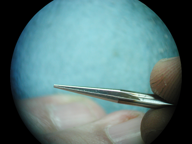
3. AFTER MACHINING: some defects are still visible and will be corrected by spot weld placement.
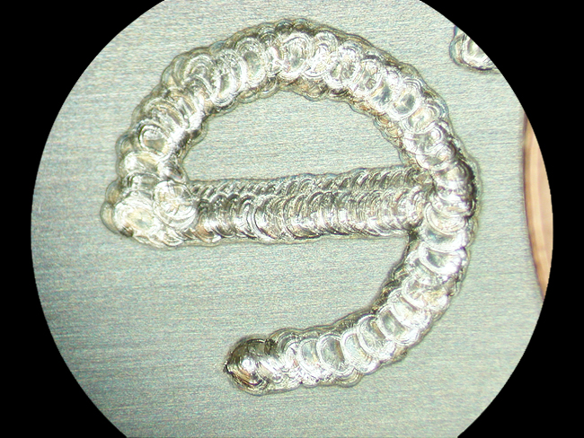
4. SPOT REPAIR

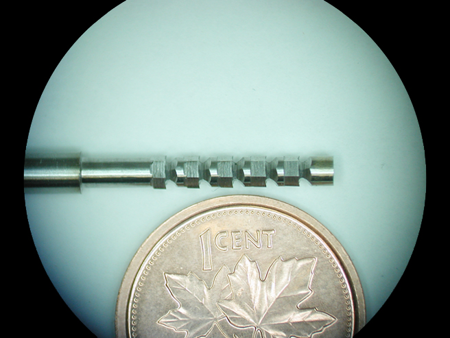
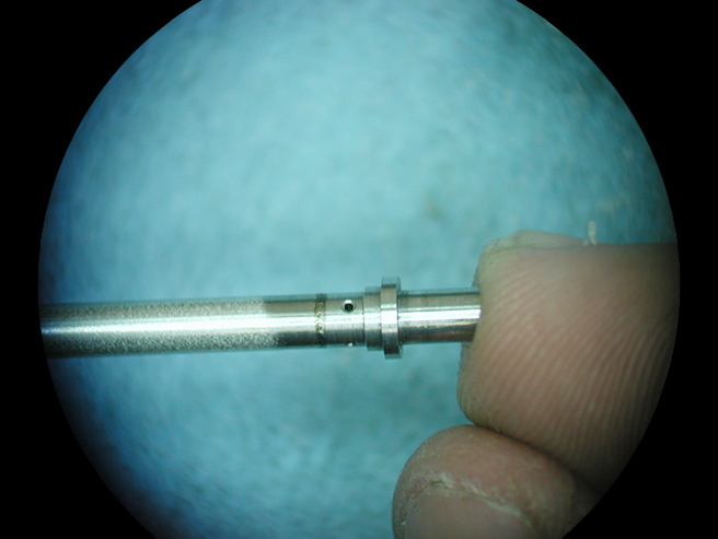
5. FINAL FINISHING: At approximately 40X magnification, the defect is barely discernable, and is completely invisible to the naked eye.

laser welding: mold repair: changing engraving

The engraving was changed per customer request.

The surface geometry to enable re-machining the insert was not available, therefore the welding needed to be delicate, allowing it to be re-finished using only polishing stones. On the left side, a logo has already been welded and hand stoned to 600 stone finish.

1. The lettering is approximately 1/8” (3.2mm) tall. The welds stand proud of the surface less than 0.003” (0.1mm). The material is P20 mold steel.

2. A DETAIL SHOT: (From another insert with slightly larger letters)

bevel gear

Here is a tiny prototype bevel gear for the surgical screwdriver featured on the homepage. It is hardened 17-4 PH stainless steel and is ¼” diameter (about 6.5mm).It was completely fabricated in-house, including CNC turning, broaching, and CNC sinker EDM on the teeth.

200 of these parts were initially run in our plant: the part is now made in a metal injection mold built by Implant Mechanix Inc.

tiny broach

This is the tool used to make the hex bore in the bevel gear blank shown below. It is ground from High Speed Steel and is 0.090” (approximately 2¼ mm) across the flats at the big end. It is progressive; each tooth removes approximately 0.001” of material, and the guiding elements between teeth keep the broach perfectly centered.

This custom tool was built to solve a concentricity and finish problem with conventional push broaching and wobble broaching.

world’s smallest dovetail cutter

This cutter is 0.062” across the points and is form ground from carbide.

The larger plastic part was modified from a molded part using the dovetail cutter; the smaller part was machined from bar.

200 units were produced using 4 axis CNC milling for product testing.
Implant Mechanix Inc later built two plastic injection molds to produce these parts in quantity. You’re looking at the parts from those molds.

tiny turned plasma nozzle and tooling

Here is the turned part: It is ½” long (about 13 mm) and has a tiny tapered through bore.

And here is the reamer used to make the bore: It is ground in-house from High Speed Steel, has 3 flutes and is 0.022” diameter at the tip (approximately ½ mm).

The reamer inserted into the part

Laser welding the inner tube to the nozzle.

Laser welding the outer tube. For more regarding laser welding, follow this link.

form ground parts

These are other surgical screwdriver parts.They were CNC milled from 303 stainless steel, form ground on the curved surface, and tumbled to finish. Quantity was 400 parts. These parts are also now metal injection molded from a mold built by Implant Mechanix Inc.

SIMPLE GANG FIXTURE:
Makes 10 parts at a time with minimal burring and no part distortion. The fixture was kept very simple because it was scheduled to retire after only 400 parts.

THE FIXTURE IN USE:
Machining time is about 12 seconds per part. The grinding wheel was shaped using a Diaform profile grinding wheel dresser.

CROSS SECTIONAL PROFILE:
The wall thickness is 0.025” (just over ½ mm).

Newer posts

© 2025 IMPLANT MECHANIX

Up ↑